Archive for the Crazy Plans Category

The MKII Robot Controller

Posted in Crazy Plans, Hardware on 29 January, 2014 by Alec Waters

I thought I’d briefly share the latest gadget I’ve been tinkering with. You may remember the robot I built for HackFu – I always thought I could do better with the packaging of the controller unit. It was in three pieces, namely the camera receiver, the TV, and the control unit itself:

wirelesscontrollerIn a fit of Wii U inspiration, I’ve managed to get all three components into a single, portable enclosure:

botcontrollerfront

There’s a convenient carry handle on the top, handholds left and right, and you operate the sticks with your thumbs. The screen is one of those cheap TVs you get for use in your car.

The AV receiver’s antenna and tuning knob poke out behind one of the hand-holds. It doesn’t get in the way of your fingers, and the tuning knob has fortuitously ended up in a very convenient place:

botcontrollertunerThe antenna will fold through 180 degrees so it won’t catch on anything when you’re not using it. Next to the antenna is the secondary AV input for the display – by changing channels you can switch from the wireless camera feed to an external one. This means you can do things like hook up another Arduino with a Video Game shield and play Tetris:

botcontrollertetrisHere are some action shots showing the telemetry overlay and the bot itself, TempEx One:

botcontrollerscreen

botcontrollerandbotWith the lid off you can see the XBee for communicating with TempEx and the arrangement of the AV receiver and Arduino:

botcontrollertopoffThere’s a single 12v DC input jack in the bottom left that powers everything.

Things still on the TODO list include:

  • Swap the XBee for one that supports an external antenna. This will be mounted in the left hand hold, flipping up and down like the AV antenna does
  • Addition of a speaker for the camera audio
  • Find a compact 12v battery to remove the need for mains power (any suggestions?)
  • Spray it a suitably impressive colour 🙂


Alec Waters is responsible for all things security at Dataline Software, and can be emailed at alec.waters@dataline.co.uk

HackFu 2013 challenge teardown – Part Two

Posted in Crazy Plans, Packet Challenge on 24 September, 2013 by Alec Waters

Part One of this post is here; this time I’m going to talk about TempEx and its controller:

rover-final

I for one welcome our new robot overlords

wirelesscontroller

TempEx One! You muussst obeeeeeeyyyyy me!

Parts list

From the point of view of the challenge, TempEx is mostly chrome, but we all know that this is the element upon which all coolness is built and we should seek it out with ruthless determination. The core of TempEx is a DFRobotShop rover which is basically a stretched Arduino UNO with tracks and motors. The tracks, wheels and gearboxes are all standard Tamiya model parts, with custom brackets holding the whole lot to the mainboard. It’s a pretty nifty bit of kit, but it needs a bit more than the basic kit to be truly useful.

Firstly, it needs a bit more payload space; this is easily catered for with the expansion plate which sits above the mainboard on standoffs. This gives you considerably more space to work with:

expansionplate

There are plenty of cut outs that you can use to mount equipment, including holes specifically for mounting servos. In terms of payload, TempEx needed to carry an infra-red camera and a rangefinder on a steerable mount like this one from Dagu. Controlling servos with an Arduino is pretty straightforward in concept although surprisingly challenging to execute in an elegant fashion, but we’ll get on to that a bit later on.

The rangefinder is an HC-SR04, which can be had on eBay for a couple of pounds. It’s easy to use (even easier with a decent library) and pretty accurate for the price, although you need to get a good return “bounce” to get a reading – if you’re facing a surface at 45 degrees to the sensor you’re not likely to get a return at all.

I scored a cheap 900Mhz IR camera on eBay:

wirelesscam

The camera can be driven from a 9v battery which gets drained pretty quickly, even more so when it’s dark and all the IR LEDs are turned on. To get around this I used lithium ones which when I tested them gave over five hours of service with no degradation in picture or signal, easily long enough to last through each team’s attempt at the challenge.

At this point, we’ve got enough gear to build a rover that you can drive around tethered via USB – not entirely practical. Two choices for wireless control are Bluetooth and ZigBee/XBee. I wanted to have a controller that worked without a PC so I went for the XBee option because it came with two radios, one for the rover and one to put in the controller.

Conceptually, control of the rover is straightforward. The ‘wasd’ sample is a useful base, reading a character from the serial port and operating the two motors accordingly:

int E1 = 6; //M1 Speed Control
int E2 = 5; //M2 Speed Control
int M1 = 8; //M1 Direction Control
int M2 = 7; //M2 Direction Control

void setup(void)
{
  int i;
  for(i=5;i<=8;i++)
  pinMode(i, OUTPUT);
  Serial.begin(9600);
  Serial.println("setup");
}

void loop(void)
{
  while (Serial.available() < 1) {} // Wait until a character is received
  char val = Serial.read();
  int leftspeed = 120; //255 is maximum speed
  int rightspeed = 120;
  switch(val) // Perform an action depending on the command
  {
    case 'w'://Move Forward
    case 'W':
      forward (leftspeed,rightspeed);
      break;
    case 's'://Move Backwards
    case 'S':
      reverse (leftspeed,rightspeed);
      break;
    case 'a'://Turn Left
    case 'A':
      left (leftspeed,rightspeed);
      break;
    case 'd'://Turn Right
    case 'D':
      right (leftspeed,rightspeed);
      break;
    default:
      stop();
      break;
  }
}

void stop(void) //Stop
{
  digitalWrite(E1,LOW);
  digitalWrite(E2,LOW);
  Serial.println("stop");
}

void forward(char a,char b)
{
  analogWrite (E1,a);
  digitalWrite(M1,LOW);
  analogWrite (E2,b);
  digitalWrite(M2,LOW);
  Serial.println("forward");
}

void reverse (char a,char b)
{
  analogWrite (E1,a);
  digitalWrite(M1,HIGH);
  analogWrite (E2,b);
  digitalWrite(M2,HIGH);
  Serial.println("reverse");
}

void left (char a,char b)
{
  analogWrite (E1,a);
  digitalWrite(M1,HIGH);
  analogWrite (E2,b);
  digitalWrite(M2,LOW);
  Serial.println("left");
}

void right (char a,char b)
{
  analogWrite (E1,a);
  digitalWrite(M1,LOW);
  analogWrite (E2,b);
  digitalWrite(M2,HIGH);
  Serial.println("right");
}

I ended up with a nine-way control of q/w/e, a/s/d, and z/x/c using ‘s’ for stop and q, e, z, and c for large-radius turns running one track at full speed and the other somewhat slower. a and d were for zero-radius turns where the rover spins on the spot.

Moving from a USB tether to wireless via XBee was straightforward. Out of the box the XBee radios act as a kind of cable replacement – whatever one transmits the other receives. Leaving aside the security implications of this default config (and the hacker-rich environment in which TempEx had to operate) moving away from the tether starts by using the XBee to serial board that comes with the rover kit.

dfrobot-xbee-usb-adapter-v2

This appears to a PC as a serial port so you can just attach a terminal app to it and enter characters just like you would in the Arduino serial monitor window. The final step is to ditch the USB port altogether and use the serial TX/RX lines with a second Arduino, again just sending single characters for the rover to interpret.

There were a couple of gotchas along the way. Firstly, the rover would occasionally throw a track when turning, something that could be seen as a result of the sprocket wheels slowly moving outwards on their axles. I was a bit reluctant to glue these in place, but fortunately no tracks were shed during HackFu.

Secondly, I had trouble with power brownouts, especially when doing something like going from full forwards to full reverse. I made three changes to cater for this:

  • Moar axle grease! A tube of this comes with the gearbox for a very good reason.
  • I switched from using the 3.7v LiPo battery to the 4xAA holder. Using rechargeable NiMh AAs gave a voltage of between 5 and 6 volts, about double the nominal voltage of the included motors. The rover went like a rocket with the AAs driving these, but at a cost. Adam Borrell has done some testing with motors like these running under over-voltage conditions. I’m glad I read this before HackFu because the brushes can wear out in a matter of hours – after all of the development hours TempEx had on the clock there was a distinct possibility that the motors would fail during the event. I replaced the 3v motors with 6v ones, and made sure I had spares on the day.
  • Finally, I re-wrote the code to be a little kinder on the drivetrain. Instead of slamming the motors from zero to max revolutions in one hit, I gently ramped the RPMs up so that it took about half a second to get to top speed.

Operating the pan/tilt rig was done in a similar way to the motors, using r/t/y, f/g/h and v/b/n, with t being down, f for left, r for down/left etc. g centred the rig forwards. Similar “kind” code was written for the servos – if slamming a motor from zero to max is unkind, doing the same with a servo is plain brutal! With the mass of the camera to shift as well as the rig itself, it’s important that the servo take its time to reach the desired rotation. For each pass through the Arduino’s loop() the servo would ask “have I rotated far enough yet?” and if not it shifted another couple of degrees towards the goal.

Here is some sample code that moves a servo “kindly” under the command of a Wii Nunchuk to illustrate:

#include <Servo.h> 
#include <Wire.h>
#include <ArduinoNunchuk.h>

#define BAUDRATE 19200

ArduinoNunchuk nunchuk = ArduinoNunchuk();
Servo myservo;  // create servo object to control a servo 
 
int potpin = 0;  // analog pin used to connect the potentiometer
int val;    // variable to read the value from the nunchuck
int servopos; // where the servo is
int threshold = 8; // trigger for movement

void setup()
{
  ///////////////////
  // SERIAL
  Serial.begin(BAUDRATE);
  ///////////////////
  
  ///////////////////
  // NUNCHUK
  nunchuk.init();
  nunchuk.update();
  servopos = map(nunchuk.analogX, 25, 221, 0, 179);     // Get initial value
  ///////////////////
  
  ///////////////////
  // SERVO
  myservo.attach(9);
  myservo.write(servopos);  // initialise position
  ///////////////////  
}
 
 
void loop() 
{ 
  nunchuk.update();

  val = map(nunchuk.analogX, 25, 221, 0, 179);     // scale it to use it with the servo (value between 0 and 180) 


  Serial.print(nunchuk.analogX, DEC);
  Serial.print(' ');
  Serial.print(val);
  Serial.print(' ');
  Serial.print(servopos);
  Serial.print(' ');  

  if( ( servopos < val ) && ( val - servopos > threshold ) )
  {
    // Moving to the right
    servopos += int( threshold / 2 );
    Serial.println('R');
  }
  else if( ( servopos > val ) && ( servopos - val > threshold )  )
  {
    // Moving to the left
    servopos -= int( threshold / 2 );
    Serial.println('L');
  }
  else
  {
    // Not moving!
    Serial.println("STOP");    
  }
  
  if( servopos < 0 )
    servopos = 0;
  else if (servopos > 179 )
    servopos = 179;
    
  myservo.write(servopos);                  // sets the servo position according to the scaled value 
  delay(10);                           // waits for the servo to get there 
} 

It just goes to show, it ain’t what you do, it’s the way that you do it:

Moving swiftly on…

…to the controller. There are four bits to this:

  • An Arduino Uno
  • An XBee radio sitting on the aforementioned USB adapter hooked up to the Arduino’s serial port
  • A pair of two-axis potentiometers, one for controlling the rover and one for steering the pan/tilt rig
  • A Nootropic Design Video Experimenter board, a bundle of awesome if ever there was one. The output of the camera receiver plugs into the video input, with a TV on the video out

The whole lot fit quite nicely into an OKW enclosure that I had left over from the now-defunct PierToPier.net WiFi project (a fully-routed mesh wireless network on Brighton beach for public use – ten years ago!).

The mode of operation is as follows:

  • Read the x and y values from the two sticks and convert them to the wasd-style character
  • Send the character to TempEx by printing it to the serial port, which sends it to the XBee, which sends it to the other XBee on TempEx where the rover’s code takes over
  • TempEx acts on the received character and takes a reading from the rangefinder. This is sent back to the controller via the XBees
  • Back on the controller, read the range from the serial port and use the Video Experimenter board to overlay it on the TV feed from the camera
  • Repeat 🙂

Step one was an interesting coding challenge – converting a pair of 0-to-255 values to a quadrant in a 3×3 grid in an elegant and efficient manner. I don’t want to blab my method here because I want to use it as a teaching case in the Arduino workshops I’ll be running soon. If you want a hint, contact me via Twitter and I’ll give you a nudge in the right direction.

The VE board displayed a bit more than just the range – I wanted it to look a bit like a heads up display in a military aircraft:

Tower, this is Ghostrider requesting a flyby

The Pan/Tilt markers have indicators that show in which direction you’re steering the camera, the L/R indicator shows which direction the two tracks are moving in, the range is at the bottom, comm errors are shown at the top, and the targeting reticle in the middle is there to make you feel extra-menacing. Here’s a less-than-clear shot of it in action at HackFu:

TempExHUD2

The VE’s overlay was a little light but perfectly legible despite what the picture above looks like. I found that by feeding the camera receiver into a VCR and attaching the VCR to the VE board produced better results, showing that the problem is more likely the output of the camera transmitter rather than the VE board.

I wanted to cater for the case where comms with TempEx were interrupted due to interference or excessive range, so in an attempt to implement reliable control the following steps were taken:

  • If neither joystick is deflected from its home position the controller continually sends ‘s’ (stop) to TempEx. If the controller gets a range in return it knows that TempEx is still there. If we don’t get anything back for two seconds, display NO COMM on the HUD to let the user know.
  • When a joystick is moved, continually send the indicated character to TempEx. This means that, moving or not, TempEx is expecting to receive something from the controller all the time. If TempEx doesn’t hear anything for two seconds it will stop both tracks and centre the pan/tilt rig.

This means that you can never have the case where TempEx runs off out of control if the wireless comm breaks down (it doesn’t stop teams from hitting obstacles at oblique angles and tipping TempEx over, but that’s another story!)

So there you have it, TempEx and its controller. I had a ton of fun putting the challenge together, and I think people had fun playing it. As I’ve said, HackFu is beyond awesome – keep your ear to the ground sometime next Spring here, here and here for a chance to win a ticket for HackFu 2014. Maybe see you there!


Alec Waters is responsible for all things security at Dataline Software, and can be emailed at alec.waters@dataline.co.uk

HackFu 2013 challenge teardown – Part One

Posted in Crazy Plans, Packet Challenge on 9 July, 2013 by Alec Waters

Words have not yet been invented to describe the utter awesomeness of HackFu. Run by MWR Infosecurity, it’s two extremely intense days of team-based hacking, puzzling and pwning, tackled by meanshackfu of skill, luck and sometimes even outright cash bribery (Facebook photo albums here and here). Many thanks to the RAF Air Defence Radar Museum for providing the venue – it’s a great place to visit, go check it out!.

As with last year, I supplied a challenge for the event. I’m going to document it here, because it was a little, errm, “different”, and I learned an awful lot whilst I was screwing it together. HackFu is all about learning stuff, and there’s no point in learning without sharing the knowledge, right?

tl;dr

Booby trapped Aztec temple. Violent kinetic defences. Golden Idols for the taking. Robots with night vision and sonar. Four distinct forms of wireless comms.

Enter the Maze…

All HackFu events are themed, and this year’s theme was The Crystal Maze. My challenge was for the Aztec zone, and had quite a straightforward aim – retrieve the Golden Idol from the altar in the temple and discover its full name. It’s not going to be as easy as walking in there and picking it up – as this journal entry shows, we could be entering a high-threat environment. How to minimise the risk? In “The Phantom Menace,” Rune Haako was faced with a similar situation: “Are you brain-dead? I’m not going in dere with two Jedi. Send a droid.”

Send a droid, you say? Enter TempEx One, the remotely operated temple explorer:

rover-finalTempEx allows the players to reconnoitre the temple, detect traps, discover clues, and ultimately permits them to formulate a plan to safely enter and retrieve the Golden Idol from the altar. TempEx is equipped with an ultrasonic range finder and a wireless infra-red camera, both mounted on a steerable pan/tilt mount.

TempEx is remotely controlled by means of a two-stick controller, shown here with its lid off:

wirelesscontroller
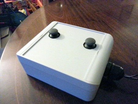
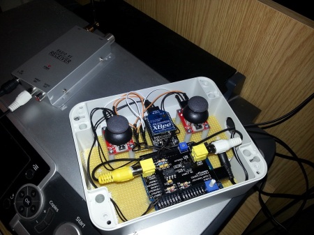
The left stick drives TempEx; the right one operates the pan/tilt rig. The camera receiver is shown in the background, and its output is pumped through a TV overlay board. This means I can draw a nice heads-up-display over the camera feed that shows command inputs from the sticks, telemetry received from TempEx, and a cool targeting reticle to make the user feel extra-menacing. With the lid on, only the sticks poke out:

controllersmallAnd the altar? It’s equipped with:

  • A light sensor – keep it dark in there, or face the consequences!
  • A pressure pad – remember what happened to Indy when he tried to swipe the Idol in Raiders of the Lost Ark!
  • Tripwires – careful where you step!
  • Active defences – eye protection mandatory!

Finally, we have the gameplay element of the challenge. It’s got to be fun, it’s got to be do-able, it’s got to have scoring in order to rank the teams, and it has to involve some hacking (otherwise the event would just be called “Fu”)

Hopefully…

…I’m keeping your attention. I built and coded all of the hardware above, and I’m going to document it one piece at a time. It’s a journey of discovery in which I struggle to remember which end of a soldering iron to hold and am forced to deploy several “Plan B’s” in pursuit of realising my ideas.

The Altar

The altar is basically an Arduino Mega 2560 mounted inside an appropriately decorated biscuit tub with one of my kids’ toys on top to give the Golden Idol somewhere to sit. It’s a pretty squat assembly, but from TempEx’s point of view seven or eight inches off the ground it looks pretty tall, especially with the idol sat on the top:

altar

The Golden Idol is definitely made of gold, honest:

goldenidol

I’d never touched an Arduino before embarking on this challenge, but when you take a look at the ingredients in an Arduino Boffin Kit things like tripwires and light sensors suddenly don’t seem impossible to implement. Books like Beginning Arduino confirm the suspicion – it’s all possible, and even relatively straightforward.

For the hardware side of the Altar, I wanted four tripwires, some kind of pressure pad, and a light sensor. I also wanted to have some kind of visual indication that the pressure pad was being read, so that people could time some kind of Indy-style switchout, taking the Golden Idol and replacing it with something else. The idea was that players would start with a given points score which would be deducted from when they trip the traps. Tripping the light sensor and pressure pad were considered major sins when compared to tripping the wires – I wanted to guard against people just turning on the lights and swiping the Idol without “playing the game”.

Let’s start with the tripwires. They’re basically switches, and that’s what I used for my first prototype. From the Arduino’s perspective, they were normally-open switches attached to digital pins configured as INPUT_PULLUP – this means that they will read high until they are dragged low, in this case by my switches being closed.

The pressure pad and light sensor were implemented as a force-sensitive resistor and a light-dependant resistor. Both were configured in series with a fixed-value resistor, forming a voltage divider. This means that by attaching the voltage divider’s Vout to an Arduino analogue pin I can determine “how much weight is on the pad” and “how light it is in the room”.

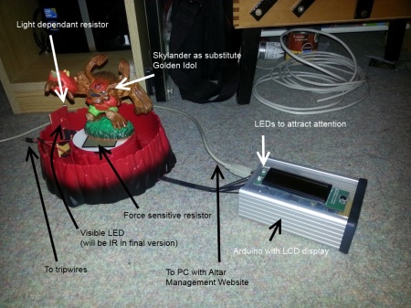
The first prototype for the Altar looked like this, built in the traditional fashion on breadboard with jumper wires:

altarprototypemarkedup
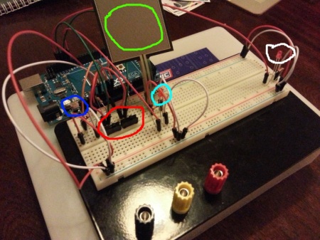
The light-dependant resistor is highlighted blue; red shows two switches pretending to be tripwires (there were four in the final version), green is the force sensitive resistor and cyan shows an LED that flashes when the FSR is being read. The LED highlighted white was used as a debugging aid to show me when all the traps were tripped. The Arduino sketch for all of this was reasonably straightforward (final version is shown later on).

Great! It’s the Altar done! Check it off the list!

Orrrrr, not. What we have here is strictly a prototype, knocked up over the course of an evening. This isn’t a deployable solution – we’ve got to “make” something, based upon the breadboarded proof of concept.

The tripwires were the easiest bit. On the breadboard above, the switches were normally-open (causing the INPUT_PULLUP pins to read high) until they were closed (causing the pin to read low). To replicate this, I took some clothespegs and drilled holes in the pads and ran wires through them:

tripwire-close
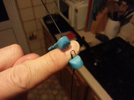
The idea is that when the peg closes the two wires touch, making the circuit and pulling the Arduino pin low. To (perhaps unnecessarily) aid conduction, I wrapped the ends in foil, resulting in this:

tripwires
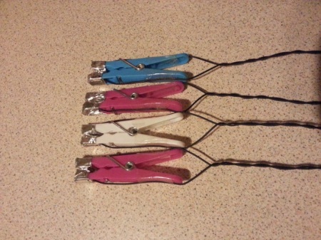
OK, now we’ve replicated the switches on the breadboard. How to make these into practical tripwires? To keep the pegs “open”, I used strips of plastic cut from a drinks bottle. Next, I tied some fishing line to the strip and anchored the other end to a fixed point. The net result is a working tripwire – if you knock the fishing line, you’ll pull the plastic strip out of the peg, which will make the circuit and cause the Arduino pin to read low, telling it that the wire has been tripped. Boom!

The FSR, LDR and flashing LED were a slightly different proposition – I had to get out the soldering iron and fabricate a circuit on stripboard. I wanted to take a modular approach, so I soldered some stackable pin headers onto the stripboard so that I could run removable wires from it back to the Arduino. More stackable headers were used as “sockets” for the tripwires. The finished stripboard is the rectangular affair that can be seen standing proud of the rim of the Altar in the picture below:

altarprototype4I mounted the Arduino in a case I had lying around; the case was eventually mounted in the decorated biscuit tub that you can see sitting under the Altar in the first picture of it above.

I have got an LCD display attached to the Arduino, from a dirt-cheap “lucky bag” from Maplin. This was originally intended to be part of the challenge, showing several lines of clues for the players. I got caught up in the fun of hooking up the display and I had it all working nicely before I realised the obvious – TempEx’s camera is an active IR one. This means that it has an IR-sensitive camera surrounded by a ring of IR LEDs – basically infra-red torches. This means that, when viewed on the camera, the LCD display is completely obscured by the reflection of the IR LEDs and you can’t read a single thing on it… Cue Plan ‘B’, which involves having the clues on a piece of paper hidden somewhere in the temple. Crude and low tech, but gets the job done!

We’re nearly there with the Altar. It can detect intrusions with all its various sensors – all it needs to be able to do is ward people off. My eldest son was suggesting things we could do when the traps were tripped, and his least lethal suggestion was to shoot them with a Nerf gun. Fortunately, MWR have a Nerf Vulcan in the corporate toybox – all I had to do was hook it up.

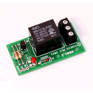
I wasn’t keen on destructively modding the Vulcan. Instead, I put a strip of plastic in the battery compartment between one of the spring terminals and the adjacent battery, with long wires snaking out of the compartment from each side of the strip. By turning on the Vulcan’s power and taping the trigger shut it can now be fired by touching the ends of the wires together. Satisfied that it’s working like this, we can put the ends of the wires into a relay that we can control from the Arduino – at this point, we have an Arduino-controlled Nerf gun, which is extremely cool in itself. I used a convenient relay board for this, having the relay energise for two seconds when one of the tripwires was pulled – this was sufficient to unleash a volley of about 6-7 darts.

relayboard

As interesting as the Altar hopefully is, it doesn’t pose much of a hacking challenge – something else is needed. Time to put the soldering iron away and think about the “gameplay” element of things.

The idea was that the altar would have a “remote management” interface which, when discovered and activated, would allow players to:

  • See the status of the traps
  • Decrease the polling interval of the FSR (to make it physically possible to swap the golden idol for a stone one)
  • Increase the trip threshold of the light sensor (so that you can send someone in with a glowstick so they can see where they’re going).

The altar management interface was implemented as a simple set of web pages on a small PC attached to the Arduino in the altar via USB. Communication was by means of a simple serial protocol over the emulated serial port that appears when you connect the two together (/dev/ttyACM0 in my case).

Here’s where a slight oddity of the Arduino platform threw a spanner in the works. By default, when you open a serial port the DTR line goes low for a short period of time. This “DTR waggle” is seen by the Arduino, which then performs an auto-reset (reboot) and starts running the sketch from scratch. This is somewhat problematic if you’re trying to keep track of someone’s score!

There’s a page on the Arduino site devoted to disabling this feature. I wasn’t keen on physically altering my Mega, nor could I make any of the software solutions work. I found another solution here – by executing “tail -f /dev/ttyACM0” on the PC, the serial connection is kept open and my scripts could talk to the Arduino without resetting it.

So now the traps are set, the remote management interface is deployed, and the Altar can be controlled via a PC. Here is how the challenge was intended to be played:

  1. From the safety of a room outside the temple, read the journal entry and TempEx manual.
  2. Cautiously open the door to the darkened temple. This will trip the tripwire controlling the Vulcan, causing the player to get a bunch of Nerf darts in the head. Aside from being for the amusement of the challenge creator, this step is designed to put players on edge and make them more cautious than they need to be. But mostly it was for the amusement of the challenge creator.
  3. Send in TempEx and have a look around. Things it will see include the Golden Idol sitting on the Altar at the far end of the room (with a light that’s flashing really fast), the tripwires, a stone Idol, and if you look hard enough, some clues written on the wall (these were the clues that I intended to show on the LCD).
  4. The clues list some “control codes” to turn “remote management” on and off. There is also the statement that something is “listening on: xx:xx:xx:xx:xx:x”.
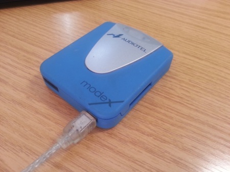
  5. The xx:xx.. thing looks a bit like a MAC address, but it’s not – it’s one nybble short in the last byte. It’s actually a phone number, and you can turn remote management on and off by sending the command codes to it via SMS. The codes are received by a GPRS modem (below) attached to the PC, and are parsed by a script run by gsmsmsd.
    gprsmodemThe script checks the content of the message, and will communicate with the Arduino if an appropriate message is present. A response message is then sent to the sender informing them of the result. I implemented a couple of commands for my own purposes, including retrieving the current trap status and score, and resetting all the trap statuses.
  6. If remote management has been turned on, the player receives the following message: “Probing for – 4zt3c : Listening on – 192.168.99.100:80 – Access Token – Sallah : Password – Kobayashii”. Oddly enough, gsmsmsd seemed to duplicate the last character when sending the reply, hence the two i’s when only one is in the script.
  7. Hopefully, the word “probing” will make the players think of wifi and set up an access point serving up an SSID of “4zt3c” (hostapd or airbase-ng could be used for this).
  8. Once the Altar has connected to your wireless network, we dutifully connect a web browser to http://192.168.99.100, as directed by the SMS. A login screen appears:
  9. management…but the supplied Access Token and Password don’t work. Whoops. Investigation of the page source shows some client-side validation JavaScript that attempts to prevent the use of several characters including <, > and ‘
  10. Knowing that most of the players will be skilled pentesters, I was hoping that they would see this as a potential indicator of a SQL Injection vulnerability. Sure enough, bypassing the JavaScript and supplying values with single quotes in them causes a MySQL error to be displayed…
  11. …but there isn’t a MySQL database, let alone a SQLi hole. The entire site is fake, designed to make people waste their time. Nothing you can enter into the form will log you in, because there’s nothing to log in to. Deception is a completely valid defensive technique!
  12. Examination of the HTTP host headers sent by the server shows that there’s one called “nazcaTrail” whose value is “clupea_harengus_russus_0120-bona_fide_0177322”. “Clupea Harengus Russus” roughly translates as “red herring”, and 0120 is 80 in Octal. The message I was trying to send was that the red herring is on port 80, and the “bona fide” site is on port 65234 (decimal representation of the octal 0177322).
  13. Finally, we have a site we can log in to at http://192.168.99.100:65234. Sure enough, it shows the state of all the traps and offers a facility to tweak the pressure pad polling interval and light sensor trip threshold. There is also a schematic of the altar showing how it all hangs together.
  14. After tweaking the pad’s polling interval, TempEx’s camera will show the Altar’s light flashing much more slowly. A brave adventurer will go in, pick up the stone idol, negotiate the tripwires, and will attempt to swap the stone idol for the golden one on the Altar in between light flashes. Except they can’t see the flashes because the LED is an infra-red one, and can only be seen on TempEx’s camera feed. To solve this problem some teams resorted to banging on the wall, others installed metronome apps on their phones and synced them up to the flashing of the LED.
  15. However they approached the LED problem, eventually the adventurer would emerge from the temple clutching the golden idol. Underneath the idol was written its name – the answer to the challenge! But…
  16. …the challenge asks for the idol’s full  name. Closer examination of the remote management website shows that the idol is running at 13.56MHz, which is an RFID frequency. Scanning the idol with an NFC-capable phone will tell you the idol’s surname.

Job done! Another successful quest for the Man In The Hat!

Here’s the Arduino sketch running the altar. I’m using the Metro library as a pseudo-timer to control the FSR polling interval and the update frequency of the (redundant) LCD display:

// Pseudo-timer library
#include <Metro.h>

// LCD driver code
#include <LiquidCrystal.h>

// RW,EN,RS on the LCD
int lcdRW = 42;
int lcdEN = 45;
int lcdRS = 44;

// The LEDs on the LCD
int lcdLED1 = 43;
int lcdLED2 = 40;

// The button on the LCD
int lcdButton = 35;

// initialize the library with the numbers of the interface pins
LiquidCrystal lcd(lcdRS, lcdRW, lcdEN, 48, 49, 46, 47);

// LDR to ensure darkness in the room
int LDR = 0;
int ldrLowThreshold = 200;
int ldrHighThreshold = 590;
int LDRThreshold = ldrLowThreshold;
bool ldrIsThresholdLow = true;

// FSR to check for presence of Golden Idol
int FSR = 1;
int FSRThreshold = 600;

// Tripwires - normally open, read high when untripped
#define numTripWires 4
int tripWireOne = 12;
int tripWireTwo = 11;
int tripWireThree = 6;
int tripWireFour = 7;

// Relay board - Nerf gun is attached to this
int relay = 8;

// Lights up when you trip all the traps
int alarmIndicator = lcdLED2;

// Lights up when the FSR is being polled
int fsrIndicator = 10;

// Polling speeds in milliseconds
int fsrFastPoll = 100;
int fsrSlowPoll = 1000;
Metro fsrMetro = Metro(fsrFastPoll);
bool fsrFastPolling = true;

// Health counter - your "score", deducted from when you trip traps
int health = 1400;

// Sensor penalties and tripped flags
int LDRPenalty = 300;
bool LDRTripped = false;
int FSRPenalty = 300;
bool FSRTripped = false;
int tripWirePenalty[numTripWires] = { 200, 200, 200, 200 };
bool tripWireTripped[numTripWires] = { false, false, false, false };
int tripWirePins[numTripWires]	= { tripWireOne, tripWireTwo, tripWireThree, tripWireFour };

// Display modes
const int dispModeListeningOnText = 0;
const int dispModeListeningOnValue = 1;
const int dispModeControlCodeOneText = 2;
const int dispModeControlCodeOne = 3;
const int dispModeControlCodeTwoText = 4;
const int dispModeControlCodeTwo = 5;
const int dispModeRemote = 6;
const int dispModeProbingFor = 7;
// How many modes?
const int dispModesRemoteOff = 7;
const int dispModesRemoteOn = 8;
int numModesActive = dispModesRemoteOff;

// Set inital display mode
int dispMode = dispModeListeningOnText;

// Set pseudoTimer for display
Metro dispMetro = Metro(2000);

// Holds data received on serial port
String serialInput = "";
// Is the message complete, terminated by # ?
bool serialInputMessageComplete = false;	

// Is remote management on on the PC?
bool remoteManagementActive = false;

// Phone number to listen on
String listeningOn = "07:xx:xx:xx:xx:x";

void setup()
{
	// Set up serial port for debugging
	Serial.begin(9600);

	// reserve 200 bytes for serialInput:
	serialInput.reserve(200);
	
	// Set up pinmodes
	pinMode( alarmIndicator, OUTPUT );
	pinMode( fsrIndicator, OUTPUT );	
	pinMode( lcdLED1, OUTPUT );
	pinMode( lcdLED2, OUTPUT );	
	pinMode( lcdButton, INPUT );		
	for( int tripWire = 0; tripWire < numTripWires; tripWire++ )
		pinMode( tripWirePins[tripWire], INPUT_PULLUP );	
	pinMode( LDR, INPUT );
	pinMode( FSR, INPUT );
	pinMode( relay, OUTPUT );		

	// Turn off alarmIndicator and fsrIndicator
	digitalWrite( alarmIndicator, LOW );
	digitalWrite( fsrIndicator, LOW );	

	// Turn off the LEDs on the LCD
	digitalWrite( lcdLED1, LOW );	
	digitalWrite( lcdLED2, LOW );	 
	
	// set up the LCD's number of columns and rows: 
	lcd.begin(16, 2);
	
	// Turn off relay
	digitalWrite( relay, LOW );
}

void loop()
{ 
	checkLCDButton();
	health -= checkLDR();
	health -= checkFSR();
	health -= checkTripwires();
	if( health <= 0 )
		digitalWrite( alarmIndicator, HIGH );

	updateDisplay(); 
	
	if( serialInputMessageComplete )
		processSerialInput( serialInput );
}

///////////////////////////////////////////////////////////////
// Updates the LCD
///////////////////////////////////////////////////////////////
void updateDisplay()
{
	if( dispMetro.check() == 1 )
	{	
		switch( dispMode )
		{
			case dispModeListeningOnText:
				lcd.clear();
				lcd.print( "Listening on:" );						
				break;
			case dispModeListeningOnValue:
				lcd.clear();
				lcd.print( listeningOn );									
				break;
			case dispModeControlCodeOneText:
				lcd.clear();
				lcd.print( "Control code 1:" );									
				break;
			case dispModeControlCodeOne:
				lcd.clear();
				lcd.print( "QZ = rmtmgmt on" );												
				break;
			case dispModeControlCodeTwoText:
				lcd.clear();
				lcd.print( "Control code 2:" );												
				break;
			case dispModeControlCodeTwo:
				lcd.clear();
				lcd.print( "JV = rmtmgmt off" );															
				break;
			case dispModeRemote:
				lcd.clear();
				lcd.print( "Remote mgmt: " );			
				lcd.setCursor( 13, 0 );
				lcd.print( remoteManagementActive ? "Y" : "N" );				
				break;
			case dispModeProbingFor:
				lcd.clear();
				lcd.print( "Probe for: 4zt3c" );						
				break;
			default:
				dispMode = 0;
		}
		
		// Cycle display
		if( ++dispMode >= numModesActive )
			dispMode = 0;
	}
}

///////////////////////////////////////////////////////////////
// Checks the LDR against the threshold
// Returns penalty
///////////////////////////////////////////////////////////////
int checkLDR()
{	
	int penalty = 0;
	
	if( !LDRTripped )
	{
		// Read LDR
		int val = analogRead( LDR );
 
		if( val > LDRThreshold )
		{
			penalty += LDRPenalty;
			LDRTripped = true;
		}
	}

	return( penalty );
}

///////////////////////////////////////////////////////////////
// Checks all tripwires
// Returns accumulated penalty
///////////////////////////////////////////////////////////////
int checkTripwires()
{
	int penalty = 0;

	for( int tripWire = 0; tripWire < numTripWires; tripWire++ )
	{
		if( !tripWireTripped[tripWire] )
		{
			if( digitalRead( tripWirePins[tripWire] ) == LOW )
			{
				penalty += tripWirePenalty[tripWire];
				tripWireTripped[tripWire] = true;
				
				if( tripWire == 3 )
				{
					// Fire the Nerf gun! Ahahahhahahaaaaaa!
					digitalWrite( relay, HIGH );		
					delay( 2000 );
					// Cease fire!
					digitalWrite( relay, LOW );
				}
			}
		}
	}

	return( penalty );
}

///////////////////////////////////////////////////////////////
// Checks the FSR
// Returns penalty
///////////////////////////////////////////////////////////////
int checkFSR()
{	
	int penalty = 0;
	
	if( fsrMetro.check() == 1 )
	{	
		// Turn on LED
		digitalWrite( fsrIndicator, HIGH );			
	
		if( !FSRTripped )
		{
			// Read FSR
			int val = analogRead( FSR );
			
			if( val < FSRThreshold )
			{
				penalty += FSRPenalty;
				FSRTripped = true;
			}
		}
	
		// Delay to blip the LED
		delay( 10 );
		// Turn LED off
		digitalWrite( fsrIndicator, LOW );			
	}
	
	return( penalty );
}

///////////////////////////////////////////////////////////////
// Checks status of button
// Resets sensors when pressed
///////////////////////////////////////////////////////////////
void checkLCDButton()
{
	if( digitalRead( lcdButton ) == HIGH )
	{
		resetTraps();
		digitalWrite( lcdLED1, HIGH );	
	}
	else
		digitalWrite( lcdLED1, LOW );	 
}

///////////////////////////////////////////////////////////////
// Resets everything for the next team!
///////////////////////////////////////////////////////////////
void resetTraps()
{
		// Reset health
		health = 1400;
		FSRTripped = false;
		fsrMetro.interval( fsrFastPoll );
		fsrFastPolling = true;				
		for( int tripWire = 0; tripWire < numTripWires; tripWire++ )
			tripWireTripped[tripWire] = false;
		LDRTripped = false;
		LDRThreshold = ldrLowThreshold;
		ldrIsThresholdLow = true;	
		numModesActive = dispModesRemoteOff;
		remoteManagementActive = false;		
		digitalWrite( lcdLED2, LOW );	 
}	

///////////////////////////////////////////////////////////////
// SerialEvent occurs whenever a new data comes in the
// hardware serial RX.	This routine is run between each
// time loop() runs, so using delay inside loop can delay
// response.	Multiple bytes of data may be available.
///////////////////////////////////////////////////////////////
void serialEvent() 
{
	while( Serial.available() ) 
	{
		// get the new byte:
		char inChar = (char)Serial.read(); 
		// add it to the inputString:
		serialInput += inChar;
		// if the incoming character is a #, set a flag
		// so the main loop can do something about it:
		if (inChar == '#') 
			serialInputMessageComplete = true;
	}
}

///////////////////////////////////////////////////////////////
// Processes input from the PC
///////////////////////////////////////////////////////////////
void processSerialInput( String message )
{
	if( message.startsWith( "STATUS" ) )		// Return sensor status
	{
		Serial.print( "STATUS FSR " );
		Serial.print( FSRTripped ? "T " : "N " );
		Serial.print( fsrFastPolling ? "F" : "S" );
		Serial.print( " LDR " );
		Serial.print( LDRTripped ? "T " : "N " );		
		Serial.print( ldrIsThresholdLow ? "L" : "H" );
		for( int tripWire = 0; tripWire < numTripWires; tripWire++ )
		{
			Serial.print( " TRIP " );
			Serial.print( tripWire + 1 );				
			Serial.print( tripWireTripped[tripWire] ? " T" : " N" );
		}
		Serial.print( " RMGMT " );
		Serial.print( remoteManagementActive ? "Y" : "N" );
		Serial.print( " HLTH " );
		Serial.print( health );
		Serial.print( "#" );
	}
	else if( message.startsWith( "LDRLOW" ) )	// Adjust LDR
	{
		LDRThreshold = ldrLowThreshold;
		ldrIsThresholdLow = true;
		Serial.print( "OK#" );
	}
	else if( message.startsWith( "LDRHIGH" ) )	// Adjust LDR
	{
		LDRThreshold = ldrHighThreshold;
		ldrIsThresholdLow = false;
		Serial.print( "OK#" );
	}	
	else if( message.startsWith( "FSRSLOW" ) )	// Adjust FSR
	{
		fsrMetro.interval( fsrSlowPoll );
		fsrFastPolling = false;
		Serial.print( "OK#" );
	}
	else if( message.startsWith( "FSRFAST" ) )	// Adjust FSR
	{
		fsrMetro.interval( fsrFastPoll );
		fsrFastPolling = true;		
		Serial.print( "OK#" );
	}	
	else if( message.startsWith( "REMOTEON" ) )	// Toggle remote management ON
	{
			numModesActive = dispModesRemoteOn;
			remoteManagementActive = true;
			digitalWrite( lcdLED2, HIGH );						
			Serial.print( "OK#" );
	}
	else if( message.startsWith( "REMOTEOFF" ) )	// Toggle remote management OFF
	{
			numModesActive = dispModesRemoteOff;
			remoteManagementActive = false;
			digitalWrite( lcdLED2, LOW );						
			Serial.print( "OK#" );
	}
	else if( message.startsWith( "07:" ) )	// Set phone number
	{
		listeningOn = message;
		Serial.print( "OK#" );
	}		
	else if( message.startsWith( "RESET" ) )	// Resets all the traps
	{
		resetTraps();
		Serial.print( "OK#" );
	}		
	else if( message.startsWith( "HEALTH" ) )	// Outputs health only
	{
		Serial.print( health );
		Serial.print( "#" );
	}			
	else
		Serial.print( "Uknown!" ); 

	// Done with the message now
	serialInput = "";
	serialInputMessageComplete = false;
}

In part two of this post, I’ll delve into TempEx One and its control unit – stay tuned! In the meantime, perhaps you’d like to get yourself an Arduino and start tinkering?


Alec Waters is responsible for all things security at Dataline Software, and can be emailed at alec.waters@dataline.co.uk

Virtual Private Onions

Posted in Crazy Plans, Crypto, NSM, Sguil on 8 October, 2012 by Alec Waters

If you’ve not checked out Security Onion (SO) yet, you really should. It’s a powerhouse Linux distro, running everything an analyst could need to carry out effective Network Security Monitoring (NSM). The latest beta is looking fantastic; watch the video and try it out, you won’t be sorry!

I’m not going to talk about SO itself (Mother Google has plenty of good things to say); instead I’m going to look at the underlying network infrastructure.

A major component of SO is Sguil, a distributed monitoring system that has sensor and server components that are used for monitoring the network and aggregating output from multiple sensors (you can see a Sguil schematic here to understand how it all fits together). The comms between the sensors and the server are protected by SSL, and SO builds on this with autossh tunnels to protect other traffic streams from interception. Ubuntu’s Uncomplicated Firewall (UFW) opens only the necessary ports to allow SO sensors to talk to their server, so all the installations are protected to a high degree.

If all of the connections between the sensors and the server are on your own infrastructure, this is fine (perhaps you have a management VLAN specifically for this purpose, for example). There is however another use case I can think of, where we like to use a slightly different method of sensor-to-server communications.

NSM As A Service?

Let’s say you’re in the business of selling NSM to clients, either short-term (“help me understand what’s on my network”) or long-term (“please be our NSM operators in return for huge bushels of cash”). This will probably involve dropping off SO sensor boxes on customer networks and having them all report in to an SO server back at base. The SO sensors will probably be behind the customer’s NAT and firewalls, but this doesn’t matter, the comms will still work. The network of sensors will look a bit like this:

This particular use case isn’t without issue, though – here is where I think that a slightly different approach to the underlying SO infrastructure has value. Consider the following:

  • The Sguil interface shows you that one of the agents on one of the sensors is down. How do you ssh in to fix it if the sensor is behind someone else’s NAT and firewalls? How do you even know which Internet IP address you should use to try?
  • You suspect one of the sensors is under excessive load. It’d be great to install an snmp agent on the sensor and point Munin at it to try and find the stressed metric. Again, how do we contact the sensor from back at base?
  • You want to implement a custom information flow from the sensor back to the server. You need to think about the security of the new flow – can you implement another autossh tunnel? What if the flow is UDP (e.g., snmp-trap)?
  • One of the sensors is reported lost or stolen. How can you easily stop it from connecting back to base when it’s possibly now in the hands of threat actor du jour?

One possible answer is to build a custom “underlay” network to carry all of the traffic between SO sensors and the server, catering for existing flows and anything else you think of in the future. As a side benefit, the sensors will all have static and known IP addresses, and contacting them from the server will be no problem at all.

Virtual Private Onions

We’ll accomplish this by using OpenVPN to create a secure, privately- and statically-addressed cloud that the sensors and server will use to talk to each other (sorry for using the word “cloud”!). Take our starting point above, showing our distributed sensors at client sites behind client firewalls. By “underlaying” the SO comms with an OpenVPN cloud we’ll end up with is something like this:

The client’s firewalls and NAT are still there, but they’re now hidden by the static, bi-directional comms layer provided by OpenVPN. The sensors all talk over the VPN to the server at 10.0.0.1; the server in turn is free to contact any of the sensors via their static addresses in the 10.0.0.0/24 subnet.

Details

I don’t intend for this to be a HOWTO; I want to wait until people tell me that what I’m proposing isn’t a galactic waste of time and completely unnecessary! Conceptually, it works like this:

The SO Server takes on the additional role of an OpenVPN server. Using OpenVPN’s “easy-rsa” feature, the Server also becomes a Certificate Authority capable of issuing certificates to itself and to the sensors.

OpenVPN gives the SO Server a routed tun0 interface with the IP address 10.0.0.1/24 (note routed – if we wanted to, we can give other subnets back at base that are “behind” the Server access to the SO Sensors via the VPN).

The Sensors become OpenVPN clients, using certificates from the Server to mutually authenticate themselves to it. The Sensors know to point their OpenVPN clients at the static Internet-facing IP address of the server back at base, getting a tun0 interface and a static IP address out of 10.0.0.0/24 in return.

When setting up the SO components on the Sensor boxes, the sosetup script is told that the server is at 10.0.0.1 via tun0, ensuring that all SO comms go over the VPN.

The VPN carries all traffic between Sensors and Server, be it Sguil’s SSL connections, autossh tunnels, SNMP traps or queries, raw syslog forwarding, psychic lottery predictions, anything. The Server is also free to ssh onto the Sensors via their static VPN addresses.

Advantages?

We’ve implemented OpenVPN with SO in this manner, and it works well for us. I hope this approach has some advantages:

  • It makes for easier firewalling at the Server and Sensor ends. You only need to open up one port, which is by default 1194/UDP. All of the VPN traffic is carried over this port.
  • You have deterministic sensor IP addressing, something you wouldn’t otherwise have had when your sensors were deployed on foreign networks behind NAT, firewalls, and dynamic IP addresses on customer DSL routers.
  • You don’t need to worry about setting up additional autossh tunnels when you dream up a new flow of information  between Sensor and Server.
  • You can easily talk to the sensors from the server, for ssh sessions, SNMP polls, or anything else.
  • If a sensor is lost or stolen, all you need to do is revoke its certificate at the Server end and it won’t be able to connect to the VPN (more on sensor security in a moment).

There are of course some disadvantages:

  • Complexity, which as we all know is the enemy of security.
  • Double encryption. OpenVPN is encrypting stuff, including stuff already encrypted by Sguil and autossh.
  • <insert other glaring flaws here>

Security considerations

On the Server side, keep in mind that it is now a Certificate Authority capable of signing certificates that grant access to your SO VPN. Guard the CA key material well – maybe even use a separate system for certificate signing and key generation. Also, once you’ve generated and deployed certificates and private keys for your sensors, remove the private keys from the Server – these belong on each specific sensor and nowhere else.

On the Sensor side, we have a duty of care towards the clients purchasing the “NSM As A Service”. OpenVPN should be configured to prohibit comms between Sensor nodes, so that a compromise of one Sensor machine doesn’t automatically give the attacker a path onto other customer networks.

If a Sensor machine is lost or stolen whilst deployed at a customer site, we can of course revoke its certificate to prevent it from connecting to the VPN. That’s great, but the /nsm directory on it is still going to contain a whole bunch of data that the client wouldn’t want turning up on eBay along with the stolen sensor.

I have a plan for this, but I’ve not implemented it yet (comments welcome!). The plan is to have the /nsm directory encrypted (a TrueCrypt volume? something else?), but to have the decryption key stored on the SO Server rather than on the Sensor. When the Sensor starts up, it builds its OpenVPN connection to the Server before the SO services start. Using the VPN, the Sensor retrieves the decryption key (one unique key per Sensor) from the Server (wget? curl? something else?), taking care never to store it on the Sensor’s local disk. Decryption key in hand, the Sensor can decrypt /nsm and allow the SO services to kick off.

In this way, a stolen Sensor box represents minimal risk to the client as the /nsm directory is encrypted, with the keymat necessary for decryption stored on the Server. Provided that the theft is communicated to the NSMAAS provider in an expedient fashion, that keymat will be out of reach of the thief once the OpenVPN certificate is revoked.

(Other, crazier, plans involve giving the Sensors GPS receivers and 3G comms for covert phone-home-in-an-emergency situations…)

So there you have it…

…Virtual Private Onions. Any comments?


Alec Waters is responsible for all things security at Dataline Software, and can be emailed at alec.waters@dataline.co.uk

Making sense of the results of the net-entropy experiment

Posted in Crazy Plans, net-entropy, NSM on 19 January, 2010 by Alec Waters

The rest of the net-entropy saga is listed here, but to briefly recap, net-entropy is a tool that can be used to profile the level of “randomness” of network traffic. High entropy traffic like this is usually either encrypted or compressed in nature, and I’m definitely interested in knowing about the presence of the former on my network. I’ve been using net-entropy as a general purpose “randomness detector”, something that the author didn’t really have in mind when he wrote it.

However, drawing meaningful conclusions from the results gathered can be tricky (this is nothing to do with net-entropy itself, and everything to do with the way I’m using it backwards to generically detect randomness). Some of the observed high entropy traffic will definitely fall into the “encrypted” category, like SSH and Remote Desktop. Other stuff will definitely be of the “compressed” flavour, like RTMP on port 1935.

Once this kind of low-hanging fruit has been pruned, the analyst is left with a whole load of unknown high-entropy traffic. If net-entropy’s presence is to be of any value at all when deployed this way, we have to try to make sense of the residual data in some way or another.

One tactic is to fire up Sguil and use its full-content capture to extract and examine each of the unknown high-entropy streams in turn. This is massively labour intensive, but some of the time you’ll find something interesting like HTTPS on a non-standard port (the certificate exchange at the start of the conversation is in clear text, giving you a clue). Most of the time however, you’re left looking at unintelligible garbage. Unsurprising really, given that it’s likely to be either compressed or encrypted…

Given that protocols like SSH, RDP and RTMP can most usually be identified by their port numbers alone and what’s left is unreadable junk, how are we to derive value from these other indicators from net-entropy? I can think of a couple of ways:

  • Session contextualisation
  • Session profiling on the basis of session duration and frequency, etc

Putting a high-entropy session into context isn’t too labour intensive, and sometimes pays dividends. Let’s say net-entropy has spotted a session from 1.2.3.4:25333 to 4.3.2.1:3377; the full-content capture is unreadable garbage, and the port numbers offer no clues. If we ask the question “was there any other traffic involving 1.2.3.4 and 4.3.2.1 at the same time”, we might get a hint. In this instance, there was a connection from 1.2.3.4:16060 to 4.3.2.1:21, which looks like an FTP command session judging by the port number. When we examine the full-content capture for this session, we can see passive FTP at work:

227 Entering Passive Mode (4,3,2,1,13,49).

The last two numbers denote the port that the client should connect to to transfer a file. Doing the maths, we see that (13 * 256) + 49 = 3377, so we can be pretty confident that our high-entropy traffic in this case was a file transferred over FTP.

If context can’t be established however, all is not lost – we can look at other attributes of the traffic.

A lot of the high-entropy traffic that we see is bound for random ports on IP addresses all over the world, and most of it is related to peer-to-peer apps. In the case of Skype, high-entropy TCP traffic is usually signaling traffic to SuperNodes. Traffic to a given SuperNode  will occur little-and-often for a long period of time until one of the two endpoints goes offline, so net-entropy will be sending you alerts all day long for that specific destination. However, you certainly can’t say for sure that traffic matching this profile is definitely Skype (it could be a keylogger phoning home at regular intervals, for example). As such, examination of the little-and-often class of high-entropy flow doesn’t usually yield any definitive conclusion.

What is definitely interesting is where you have many high-entropy flows to the same destination address and port in a short period of time. We have detected the following by taking this “clustering” approach:

  • HTTP on a non-standard port, serving up images (most image formats are compressed, and thereby have a high-entropy signature). As an example, some of the images in search results here come from port 7777. Someone browsing this site will trigger many indicators from net-entropy in a short space of time that refer to this port.
  • HTTP proxies. Again, the high-entropy traffic is most commonly as a result of images being transferred.
  • SSL/TLSv1 on port 8083, which turned out to be traffic to a SecureSphere web application firewall.

Clusters like this are most easily detected by eye by means of visualisation. The following image is from one of my Cisco MARS reports, and shows a cluster of traffic to port 8083 in orange:

Something “worth looking at” will usually be quite clear from an image like this.

The approach I’ve taken with net-entropy has yielded neither precise nor definitive results (which certainly isn’t a complaint about net-entropy itself – it was never designed to be used the way I’m using it). But, I’ve discovered things that I’d never have known about without it, so I reckon I’ve come out on top!


Alec Waters is responsible for all things security at Dataline Software, and can be emailed at alec.waters(at)dataline.co.uk

Detecting encrypted traffic with net-entropy, part two

Posted in Crazy Plans, net-entropy, NSM on 24 September, 2009 by Alec Waters

Back here I described my setup of a modified version of net-entropy, which I was going to use in my quest to detect encrypted traffic. Well, it’s been running for a week or so now, and I’ve got some results.

  • Did it detect encrypted traffic? Yes!
  • Did it detect stuff that wasn’t encrypted? Yes!
  • Did it fail to detect traffic that definitely was encrypted? Yes!
  • Was the experiment a total failure and a complete waste of time? No! Far from it, in fact.

The theory I was testing was that traffic with sufficient entropy might be encrypted, since high entropy is a property of decent encryption algorithms. net-entropy was set to trigger an alert if it saw any connections whose entropy crossed an arbitrarily chosen threshold of 7.9 (8.0 is the maximum), and protocols that were expected to be encrypted (HTTPS, etc.) were filtered out.

Here’s a summary of what I’ve found so far:

  • Encrypted traffic that crossed the 7.9 threshold included Windows Remote Desktop (RDP), Skype (both calls and signalling traffic), SSH-2, and Google Talk.
  • Unencrypted traffic that crossed the threshold was mainly RTMP (streaming Flash audio/video), and possibly Spotify (I don’t know for sure if Spotify uses encryption or not, but high entropy was observed both on the inbound media from port 4070 and the outbound media on random ports). Media protocols like this are usually highly compressed – high entropy is a side effect of compression as well as encryption.
  • Encrypted traffic that was not detected included SSH-1 (1.5, to be exact). SSH-2 was detected as one would hope, provided that the session was long enough.

Clearly my blunt approach of a single threshold isn’t the most effective one, as we have both false positives and false negatives. But after applying some visualisations to my results, an intriguing possibility presents itself.

net-entropy was installed in this instance on a Sguil box mainly so that it was in a position where it could see a large volume of real-world traffic. A happy side effect of this is that it’s quite simple to extract the raw traffic captures that each net-entropy alert is referring to. If we’ve built net-entropy with the –enable-statistics option, we are then in a position to draw graphs of the entropy of an individual TCP stream:

  • First, use the net-entropy alert to extract the specific TCP stream. The easiest way to do this is to search for it using the Sguil client, and then export the results to Wireshark. Let’s save the capture as session.raw
  • Then we run net-entropy over it in statistics mode:
    $ net-entropy -r session.raw -s mystatsdir -F
     -b -c net-entropy.conf
  • The output of this is a .dat file whose name is made up of a timestamp and the source and dest IP addresses and ports.
  • We can now plot this file in gnuplot:
    plot 'mystatsdir/whateveritwascalled.dat'

By way of a baseline, here is a plot showing the entropy of the first 64KB of an HTTPS and an SSH-2 session. The blue line marks the 7.9 alerting threshold:

net-entropy baseline

Zooming in a little, we can see that HTTPS crossed the threshold after about 2.2KB of data, and SSH-2 took a little longer:

net-entropy zoomLet’s zoom in a little on a different area of the graph – the little “wobble” on the SSH-2 line:

net-entropy ssh-2What we’re looking at here is the part of the conversation where the various parameters of the SSH-2 session are being exchanged (key exchange protocol, encryption/hashing algorithms, etc). These are passed as cleartext, hence the low entropy at this point.

It’s an interesting little pattern, though. Let’s overlay some more SSH sessions onto the one above and see what they look like:

net-entropy sshThere are three sessions illustrated here:

  • The blue line is an SSH-2 session, which in the context of this experiment is a “true positive” since it was encrypted and it did cross the 7.9 threshold
  • The red line is another SSH-2 session which was so short in duration it didn’t manage to make it above 7.9. This is a “false negative” because we’ve missed something that definitely was encrypted.
  • The green line is an SSH-1 session. At no point during this session’s life did it cross the 7.9 threshold – another false negative.

As far as detecting encrypted traffic goes, this clearly isn’t as useful as I’d have hoped. But look at the red and blue lines – look how tightly they follow one another:

net-entropy ssh zoom

This brings us to the intriguing possibility I alluded to earlier – using entropy analysis not for the detection of encrypted traffic, but for the classification of traffic.

What if the entropy of certain types of traffic is reasonably consistent? What if the patterns above represent “fingerprints” for SSH-1 and SSH-2 traffic? If we could match traffic against a library of fingerprints, we’d have a port-independent classifier of sorts.

I’ve not had time yet to analyse sample sets large enough to be anywhere approaching conclusive, but let’s look at some other kinds of traffic:

The following graph shows four RTMP sessions:

net-entropy rtmpWhilst RTMP isn’t encrypted, all four sessions have a similar visual fingerprint.

Now let’s look at nine RDP sessions (Windows Remote Desktop):

net-entropy rdpThe most obvious outlier here is the black line – this was an RDP session to a server whose encryption level was set to “Low”. If we zoom in a bit, we’ll see another outlier:

net-entropy rdp zoomThe orange line is significantly different to the others. This particular session sent the string “Cookie: mstshash=machinename” in the first data segment sent from the client to the server – the other sessions had mostly zeroes instead, hence the lower entropy at this point. Since this is the very first data segment in the session, we could possibly infer that we’re looking at different client software used to make the connection. Indeed, if we look at RDP sessions from rdesktop (rather than the Windows client), the entropy looks different still:

net-entropy rdp rdesktopThe entropy is low, relative to the Windows client, and there’s a slightly different signature at the start of the connection:

net-entropy rdp rdesktop zoomOne might be tempted to think that one could look at graphs like these and infer something about both the server (encryption level in use) and the client (type of software used).

OK. Enough graphs. Summary time.

Detecting encrypted traffic with a straightforward entropy threshold doesn’t seem to be useful. However, we may be able to use entropy analysis as a means to classify traffic in a port-independent manner, but I’ve analysed nowhere near enough traffic to assess whether this could be a viable technique or not (there are bound to be loads of outlying cases that don’t fit the profile). And even if it is a viable technique, are the bases already covered by other port-independent classifiers (l7filter, et al)? That said, I’m not the first person to explore various visualisations of encrypted traffic, so someone somewhere considers the broad concept useful.

Comments welcome!


Alec Waters is responsible for all things security at Dataline Software, and can be emailed at alec.waters(at)dataline.co.uk

Detecting encrypted traffic with net-entropy, part one

Posted in Crazy Plans, net-entropy, NSM on 17 September, 2009 by Alec Waters

I’ve been pondering the possibility of detecting encrypted traffic crossing a network, and I think I’m getting somewhere (not necessarily closer to the goal, but somewhere nonetheless!). My initial thoughts were to put some kind of frequency analysis to the task, and whilst I was researching this I came across net-entropy.

net-entropy is a clever tool that can learn the expected cumulative packet entropy (“randomness”) for a given protocol, and raise alerts if an observed connection falls out of bounds (there’s a very detailed writeup here). The theory is that if someone is attacking a flaw in some cryptographic software (a SSH server, for example), the observed entropy of the connection will decrease unexpectedly once the attack has been executed and the attacker is delivering shellcode or whatever (figures two and three here illustrate the principle).

net-entropy was designed to focus on its list of pre-learned protocols, each of which is described in a protospec file. Here is the file for SSH:

Port: 22
Direction: both
Cumulative: yes
RangeUnit: bytes
# Range: start    end      min_ent        max_ent
Range:   1        63       0              4.38105154
Range:   64       127      4.22877741     4.64838314
Range:   128      255      4.95194340     5.02499151
Range:   256      511      4.86894369     7.28671360
Range:   512      1023     4.86310673     7.59574795
Range:   1024     1535     4.94409609     7.74570751
Range:   1536     2047     5.77497149     7.81915951
Range:   2048     3071     6.44314718     7.85139179
Range:   3072     4095     7.17234325     7.92034960
Range:   4096     8191     7.46498394     7.96606302
Range:   8192     65536    7.82608652     7.99687433

Each range is defined in terms of start byte and end byte, and minimum and maximum entropy. For example, for the first 63 bytes, the entropy is expected to be between 0 and 4.38105154 – an alert is raised if the entropy at this point is either too high or too low.

We could have a go at detecting encrypted traffic (rather than profiling its properties) with a very simple protospec file. What I’m interested in seeing is anything with an observed entropy that’s greater than some defined threshold – this will be my indicator that what we’re looking at could possibly be encrypted. So, we could have a protospec file that looks like this:

Port: "whatever"
Direction: both
Cumulative: yes
RangeUnit: bytes
# Range: start    end      min_ent        max_ent
Range:   1        65536    0              7.9

This file will cause net-entropy to raise an alert if the entropy for a connection on port “whatever” exceeds my arbitrarily chosen threshold of 7.9 in the first 64KB of its life; the problem here is that I’d have to write thousands of these files to cover the complete set of all TCP ports. I spoke to net-entropy’s author, Julien Olivain, about this and he very kindly implemented me an “all” feature, whereby a single protospec file can be applied to the complete range of TCP ports (updated source code is available here).

Now we can start to experiment! net-entropy will accept the usual variety of capture filter, so we can use this to exclude:

  • The protocols that we expect to be encrypted (SSH, HTTPS, etc.)
  • High volume protocols that are scrutinised by other means (SMTP, HTTP, etc.)
  • Non-TCP protocols (net-entropy only works for TCP at the moment)

So, our net-entropy.conf file looks like this:

Interface: eth1
RuntimeUser: nobody
MemoryLimit: 131072
MaxTrackSize: 65536
PcapFilter: tcp and not port 80 and not port 25 and not port 22 and
            not port 443 and not port 993 and not port 995
ProtoSpec: /usr/local/share/net-entropy/protospec/proto-tcp-all.nes

I installed the software on a Sguil box and fired it up; pretty soon, things like this were popping up in /var/log/messages:

Sep 17 11:15:03 morpheus net-entropy[2689]: RISING ALARM on 212.7x.aaa.bbb:1708 -> 82.4x.aaa.bbb:60970 offset=2406 packets=7 entropy=7.90993547 range=0 (1 65536 0.000000 7.900000)

Woohoo! Data! Now all we have to do is work out if it’s useful or not. I’m not one for leaving logs lying idly on the server that generated them so I send the messages to a remote syslog collector, in this case a Cisco CS-MARS. The MARS certainly has its flaws and niggles, but it does let you write custom parsers for devices it doesn’t know about. Once the MARS has been educated in the ways of net-entropy, you can use its querying mechanism to start exploring the data.

I’ve written the required custom parsers, and exported them as a Device Support Package that you can import into your own MARS, if you happen to have one and want to play along (download it here). The net result is that I can do stuff like:

  • Ask about the kinds of messages from net-entropy:

    Event Types

    Event Types

  • See the details of sessions seen:

    Sessions

    Sessions

  • Drill down onto a single session:
    A single session

    A single session

    Note that the MARS has noticed that there are two events talking about the same session (based on the IP addresses and ports), and has been able to correlate them together into a single session.

  • Get the raw messages as raised by net-entropy:

    Raw messages from net-entropy

    Raw messages from net-entropy

So, here’s where we’re at:

  • net-entropy has been enhanced to support a protospec file that applies to all ports
  • This allows us to do “generic” entropy detection
  • Events from net-entropy are being exported to my MARS, from which I can run queries and reports

Next steps:

  • Work out if the things that net-entropy is alarming on are actually encrypted, or if the reason for their high entropy is something else (effective compression, for example). If I’m not reliably detecting encryption, then I can either tweak my entropy threshold, or give up the whole idea 😉
  • If the technique is really yielding useful results, perhaps write an agent for Sguil so that net-entropy’s alerts appear in the client for easy drill-down onto the session transcripts (there’s an agent available for modsec, so it could be feasible to try this)
  • In the far future, how about a mod to the Sguil client that lets you right-click and say “Graph session entropy”? This would extract the relevant session from the full-content capture (just like the Wireshark option does at present), run it through net-entropy in statistics mode, and use gnuplot to visualise the result.

This post is most definitely filed under “Crazy Plans”. Comments on my insanity are welcome.


Alec Waters is responsible for all things security at Dataline Software, and can be emailed at alec.waters(at)dataline.co.uk

Detecting encrypted traffic with frequency analysis – Update

Posted in Crazy Plans, net-entropy, NSM, Sguil on 2 September, 2009 by Alec Waters

I recently wrote about a plan for detecting encrypted traffic, where I mentioned in the comments that I’d come across a package called net-entropy (very detailed writeup here). I’ve been in touch with Julien Olivain, one of the authors, and he’s kindly given me the sources to experiment with.

And experiment I shall – I’ll post my findings when I’ve got some!


Alec Waters is responsible for all things security at Dataline Software, and can be emailed at alec.waters(at)dataline.co.uk

Detecting encrypted traffic with frequency analysis

Posted in Crazy Plans, net-entropy, NSM, Sguil on 12 August, 2009 by Alec Waters

Let’s start with a little disclaimer:

I am not a cryptanalyst. I am not a mathematician. It is quite possible that I am a complete idiot. You decide.

With that out of the way, let’s begin.

NSM advocates the capture of, amongst other things, full-content data. It is often said that there’s no point in performing full-content capture of encrypted data that you can’t decrypt – why take up disk space with stuff you’ll never be able to read? It’s quite a valid point – one of the networks I look after carries quite a bit of IPSec traffic (tens of gigabytes per day), and I exclude it from my full content capture. I consider it enough, in this instance, to have accurate session information from SANCP or Netflow which is far more economical on disk space.

That said, you can still learn quite a bit from inspecting full-content captures of encrypted data – there is often useful information in the session setup phase that you can read in clear text (e.g., a list of ciphers supported, or SSH version strings, or site certificates, etc.). It still won’t be feasible to decrypt the traffic, but at least you’ll have some clues about its nature.

A while ago, Richard wrote a post called “Is it NSM if…” where he says:

While we’re talking about full content, I suppose I should briefly address the issue of encryption. Yes, encryption is a problem. Shoot, even binary protocols, obscure protocols, and the like make understanding full content difficult and maybe impossible. Yes, intruders use encryption, and those that don’t are fools. The point is that even if you find an encrypted channel when inspecting full content, the fact that it is encrypted has value.

That sounds reasonable to me. If you see some encrypted stuff and you can’t account for it as legitimate (run of the mill HTTPS, expected SSH sessions, etc.) then what you’re looking at is a definite Indicator, worthy of investigation.

So, let’s just ask our capture-wotsits for all the encrypted traffic they’ve got, then, shall we? Hmm. I’m not sure of a good way to do that (if you do, you can stop reading now and please let me know what it is!).

But…

…I’ve got an idea.

Frequency analysis is a useful way to detect the presence of a substitution cipher. You take your ciphertext and draw a nice histogram showing the frequency of all the characters you encounter. Then you can make some assumptions (like the most frequent character was actually an ‘e’ in the plaintext) and proceed from there.

However, the encryption protocols you’re likely to encounter on a network aren’t going to be susceptible to this kind of codebreaking. The ciphertext produced by a decent algorithm will be jolly random in nature, and a frequency analysis will show you a “flat” histogram.

So why am I talking about frequency analysis? Because this post is about detecting encrypted traffic, not decrypting it.

Over at Security Ripcord, there’s a really nifty tool for drawing file histograms. Take a look at the example images – the profile of the histograms is pretty “rough” in nature until you get down to the Truecrypt example – it’s dead flat, because a decent encryption algorithm has produced lots and lots of nice randomness (great terminology, huh? Like I said, I’m not a cryptanalyst or a mathematician!)

So, here’s the Crazy Plan for detecting encypted traffic:

  1. Sample X contiguous bytes of a given session (maybe twice, once for src->dst and once for dst->src). A few kilobytes ought to be enough to get an idea of the level of randomness we’re looking at.
  2. Make your X-byte block start a little way into the session, so that we don’t include any plaintext in the session startup.
  3. Strip off the frame/packet headers (ethernet, IP, TCP, UDP, ESP, whatever) so that you’re only looking at the packet payload.
  4. Perform your frequency analysis of your chunk of payload, and “measure the resultant flatness”.
  5. Your “measure of flatness” equates to the “potential likelihood that this is encrypted”.

Perhaps one could assess the measure of flatness by calculating the standard deviation of the character frequencies? Taking the Truecrypt example, this is going to be pretty close to zero; the TIFF example is going to yield a much higher standard deviation.

Assuming what I’ve babbled on about here is valid, wouldn’t it be great to get this into Sguil? If SANCP or a Snort pre-processor could perform this kind of sampling, you’d be able to execute some SQL like this:

select [columns] from sancp where src_randomness < 1 or dst_randomness < 1

…and you’d have a list of possibly encrypted sessions.

How’s that sound?

This post has been updated here.

Check out InfoSec Institute for IT courses
including computer forensics boot camp training.


Alec Waters is responsible for all things security at Dataline Software, and can be emailed at alec.waters(at)dataline.co.uk