HackFu 2013 challenge teardown – Part Two
Part One of this post is here; this time I’m going to talk about TempEx and its controller:
Parts list
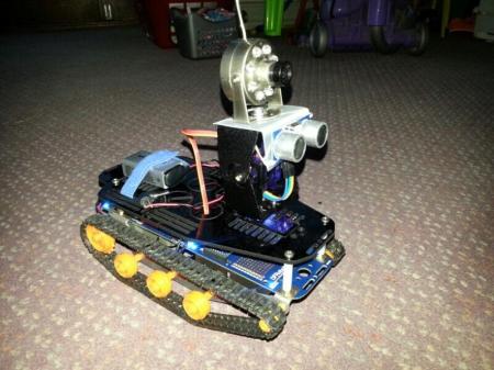
From the point of view of the challenge, TempEx is mostly chrome, but we all know that this is the element upon which all coolness is built and we should seek it out with ruthless determination. The core of TempEx is a DFRobotShop rover which is basically a stretched Arduino UNO with tracks and motors. The tracks, wheels and gearboxes are all standard Tamiya model parts, with custom brackets holding the whole lot to the mainboard. It’s a pretty nifty bit of kit, but it needs a bit more than the basic kit to be truly useful.
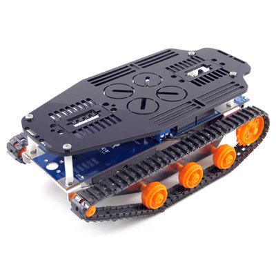
Firstly, it needs a bit more payload space; this is easily catered for with the expansion plate which sits above the mainboard on standoffs. This gives you considerably more space to work with:
There are plenty of cut outs that you can use to mount equipment, including holes specifically for mounting servos. In terms of payload, TempEx needed to carry an infra-red camera and a rangefinder on a steerable mount like this one from Dagu. Controlling servos with an Arduino is pretty straightforward in concept although surprisingly challenging to execute in an elegant fashion, but we’ll get on to that a bit later on.
The rangefinder is an HC-SR04, which can be had on eBay for a couple of pounds. It’s easy to use (even easier with a decent library) and pretty accurate for the price, although you need to get a good return “bounce” to get a reading – if you’re facing a surface at 45 degrees to the sensor you’re not likely to get a return at all.
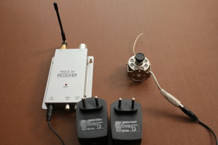
I scored a cheap 900Mhz IR camera on eBay:
The camera can be driven from a 9v battery which gets drained pretty quickly, even more so when it’s dark and all the IR LEDs are turned on. To get around this I used lithium ones which when I tested them gave over five hours of service with no degradation in picture or signal, easily long enough to last through each team’s attempt at the challenge.
At this point, we’ve got enough gear to build a rover that you can drive around tethered via USB – not entirely practical. Two choices for wireless control are Bluetooth and ZigBee/XBee. I wanted to have a controller that worked without a PC so I went for the XBee option because it came with two radios, one for the rover and one to put in the controller.
Conceptually, control of the rover is straightforward. The ‘wasd’ sample is a useful base, reading a character from the serial port and operating the two motors accordingly:
int E1 = 6; //M1 Speed Control
int E2 = 5; //M2 Speed Control
int M1 = 8; //M1 Direction Control
int M2 = 7; //M2 Direction Control

void setup(void)
{
  int i;
  for(i=5;i<=8;i++)
  pinMode(i, OUTPUT);
  Serial.begin(9600);
  Serial.println("setup");
}

void loop(void)
{
  while (Serial.available() < 1) {} // Wait until a character is received
  char val = Serial.read();
  int leftspeed = 120; //255 is maximum speed
  int rightspeed = 120;
  switch(val) // Perform an action depending on the command
  {
    case 'w'://Move Forward
    case 'W':
      forward (leftspeed,rightspeed);
      break;
    case 's'://Move Backwards
    case 'S':
      reverse (leftspeed,rightspeed);
      break;
    case 'a'://Turn Left
    case 'A':
      left (leftspeed,rightspeed);
      break;
    case 'd'://Turn Right
    case 'D':
      right (leftspeed,rightspeed);
      break;
    default:
      stop();
      break;
  }
}

void stop(void) //Stop
{
  digitalWrite(E1,LOW);
  digitalWrite(E2,LOW);
  Serial.println("stop");
}

void forward(char a,char b)
{
  analogWrite (E1,a);
  digitalWrite(M1,LOW);
  analogWrite (E2,b);
  digitalWrite(M2,LOW);
  Serial.println("forward");
}

void reverse (char a,char b)
{
  analogWrite (E1,a);
  digitalWrite(M1,HIGH);
  analogWrite (E2,b);
  digitalWrite(M2,HIGH);
  Serial.println("reverse");
}

void left (char a,char b)
{
  analogWrite (E1,a);
  digitalWrite(M1,HIGH);
  analogWrite (E2,b);
  digitalWrite(M2,LOW);
  Serial.println("left");
}

void right (char a,char b)
{
  analogWrite (E1,a);
  digitalWrite(M1,LOW);
  analogWrite (E2,b);
  digitalWrite(M2,HIGH);
  Serial.println("right");
}
I ended up with a nine-way control of q/w/e, a/s/d, and z/x/c using ‘s’ for stop and q, e, z, and c for large-radius turns running one track at full speed and the other somewhat slower. a and d were for zero-radius turns where the rover spins on the spot.
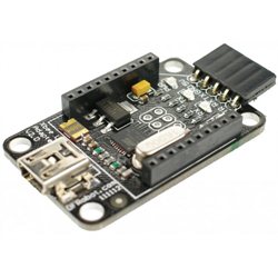
Moving from a USB tether to wireless via XBee was straightforward. Out of the box the XBee radios act as a kind of cable replacement – whatever one transmits the other receives. Leaving aside the security implications of this default config (and the hacker-rich environment in which TempEx had to operate) moving away from the tether starts by using the XBee to serial board that comes with the rover kit.
This appears to a PC as a serial port so you can just attach a terminal app to it and enter characters just like you would in the Arduino serial monitor window. The final step is to ditch the USB port altogether and use the serial TX/RX lines with a second Arduino, again just sending single characters for the rover to interpret.
There were a couple of gotchas along the way. Firstly, the rover would occasionally throw a track when turning, something that could be seen as a result of the sprocket wheels slowly moving outwards on their axles. I was a bit reluctant to glue these in place, but fortunately no tracks were shed during HackFu.
Secondly, I had trouble with power brownouts, especially when doing something like going from full forwards to full reverse. I made three changes to cater for this:
- Moar axle grease! A tube of this comes with the gearbox for a very good reason.
- I switched from using the 3.7v LiPo battery to the 4xAA holder. Using rechargeable NiMh AAs gave a voltage of between 5 and 6 volts, about double the nominal voltage of the included motors. The rover went like a rocket with the AAs driving these, but at a cost. Adam Borrell has done some testing with motors like these running under over-voltage conditions. I’m glad I read this before HackFu because the brushes can wear out in a matter of hours – after all of the development hours TempEx had on the clock there was a distinct possibility that the motors would fail during the event. I replaced the 3v motors with 6v ones, and made sure I had spares on the day.
- Finally, I re-wrote the code to be a little kinder on the drivetrain. Instead of slamming the motors from zero to max revolutions in one hit, I gently ramped the RPMs up so that it took about half a second to get to top speed.
Operating the pan/tilt rig was done in a similar way to the motors, using r/t/y, f/g/h and v/b/n, with t being down, f for left, r for down/left etc. g centred the rig forwards. Similar “kind” code was written for the servos – if slamming a motor from zero to max is unkind, doing the same with a servo is plain brutal! With the mass of the camera to shift as well as the rig itself, it’s important that the servo take its time to reach the desired rotation. For each pass through the Arduino’s loop() the servo would ask “have I rotated far enough yet?” and if not it shifted another couple of degrees towards the goal.
Here is some sample code that moves a servo “kindly” under the command of a Wii Nunchuk to illustrate:
#include <Servo.h>
#include <Wire.h>
#include <ArduinoNunchuk.h>

#define BAUDRATE 19200

ArduinoNunchuk nunchuk = ArduinoNunchuk();
Servo myservo;  // create servo object to control a servo

int potpin = 0;  // analog pin used to connect the potentiometer
int val;    // variable to read the value from the nunchuck
int servopos; // where the servo is
int threshold = 8; // trigger for movement

void setup()
{
  ///////////////////
  // SERIAL
  Serial.begin(BAUDRATE);
  ///////////////////

  ///////////////////
  // NUNCHUK
  nunchuk.init();
  nunchuk.update();
  servopos = map(nunchuk.analogX, 25, 221, 0, 179);     // Get initial value
  ///////////////////

  ///////////////////
  // SERVO
  myservo.attach(9);
  myservo.write(servopos);  // initialise position
  ///////////////////
}


void loop()
{
  nunchuk.update();

  val = map(nunchuk.analogX, 25, 221, 0, 179);     // scale it to use it with the servo (value between 0 and 180)


  Serial.print(nunchuk.analogX, DEC);
  Serial.print(' ');
  Serial.print(val);
  Serial.print(' ');
  Serial.print(servopos);
  Serial.print(' ');

  if( ( servopos < val ) && ( val - servopos > threshold ) )
  {
    // Moving to the right
    servopos += int( threshold / 2 );
    Serial.println('R');
  }
  else if( ( servopos > val ) && ( servopos - val > threshold )  )
  {
    // Moving to the left
    servopos -= int( threshold / 2 );
    Serial.println('L');
  }
  else
  {
    // Not moving!
    Serial.println("STOP");
  }

  if( servopos < 0 )
    servopos = 0;
  else if (servopos > 179 )
    servopos = 179;

  myservo.write(servopos);                  // sets the servo position according to the scaled value
  delay(10);                           // waits for the servo to get there
}
It just goes to show, it ain’t what you do, it’s the way that you do it:
Moving swiftly on…
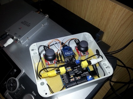
…to the controller. There are four bits to this:
- An Arduino Uno
- An XBee radio sitting on the aforementioned USB adapter hooked up to the Arduino’s serial port
- A pair of two-axis potentiometers, one for controlling the rover and one for steering the pan/tilt rig
- A Nootropic Design Video Experimenter board, a bundle of awesome if ever there was one. The output of the camera receiver plugs into the video input, with a TV on the video out
The whole lot fit quite nicely into an OKW enclosure that I had left over from the now-defunct PierToPier.net WiFi project (a fully-routed mesh wireless network on Brighton beach for public use – ten years ago!).
The mode of operation is as follows:
- Read the x and y values from the two sticks and convert them to the wasd-style character
- Send the character to TempEx by printing it to the serial port, which sends it to the XBee, which sends it to the other XBee on TempEx where the rover’s code takes over
- TempEx acts on the received character and takes a reading from the rangefinder. This is sent back to the controller via the XBees
- Back on the controller, read the range from the serial port and use the Video Experimenter board to overlay it on the TV feed from the camera
- Repeat 🙂
Step one was an interesting coding challenge – converting a pair of 0-to-255 values to a quadrant in a 3×3 grid in an elegant and efficient manner. I don’t want to blab my method here because I want to use it as a teaching case in the Arduino workshops I’ll be running soon. If you want a hint, contact me via Twitter and I’ll give you a nudge in the right direction.
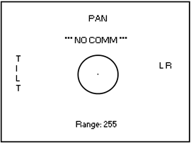
The VE board displayed a bit more than just the range – I wanted it to look a bit like a heads up display in a military aircraft:
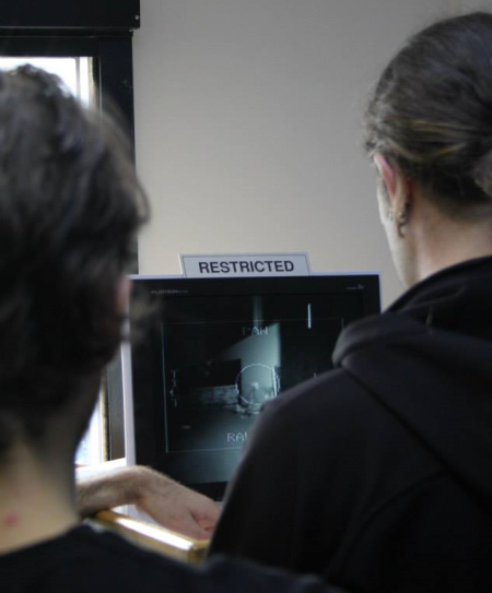
The Pan/Tilt markers have indicators that show in which direction you’re steering the camera, the L/R indicator shows which direction the two tracks are moving in, the range is at the bottom, comm errors are shown at the top, and the targeting reticle in the middle is there to make you feel extra-menacing. Here’s a less-than-clear shot of it in action at HackFu:
The VE’s overlay was a little light but perfectly legible despite what the picture above looks like. I found that by feeding the camera receiver into a VCR and attaching the VCR to the VE board produced better results, showing that the problem is more likely the output of the camera transmitter rather than the VE board.
I wanted to cater for the case where comms with TempEx were interrupted due to interference or excessive range, so in an attempt to implement reliable control the following steps were taken:
- If neither joystick is deflected from its home position the controller continually sends ‘s’ (stop) to TempEx. If the controller gets a range in return it knows that TempEx is still there. If we don’t get anything back for two seconds, display NO COMM on the HUD to let the user know.
- When a joystick is moved, continually send the indicated character to TempEx. This means that, moving or not, TempEx is expecting to receive something from the controller all the time. If TempEx doesn’t hear anything for two seconds it will stop both tracks and centre the pan/tilt rig.
This means that you can never have the case where TempEx runs off out of control if the wireless comm breaks down (it doesn’t stop teams from hitting obstacles at oblique angles and tipping TempEx over, but that’s another story!)
So there you have it, TempEx and its controller. I had a ton of fun putting the challenge together, and I think people had fun playing it. As I’ve said, HackFu is beyond awesome – keep your ear to the ground sometime next Spring here, here and here for a chance to win a ticket for HackFu 2014. Maybe see you there!

 Alec Waters is responsible for all things security at Dataline Software, and can be emailed at alec.waters@dataline.co.uk

29 January, 2014 at 19:57
[…] I’d briefly share the latest gadget I’ve been tinkering with. You may remember the robot I built for HackFu – I always thought I could do better with the packaging of the controller unit. It was in […]
29 January, 2014 at 20:33
[…] I’d briefly share the latest gadget I’ve been tinkering with. You may remember the robot I built for HackFu – I always thought I could do better with the packaging of the controller unit. It was in three […]
17 February, 2014 at 14:20
[…] Interested in learning more? You can check out Alec’s MKII robot controller blog post here and the original Arduino-based robot built for HackFu 2013 here. […]